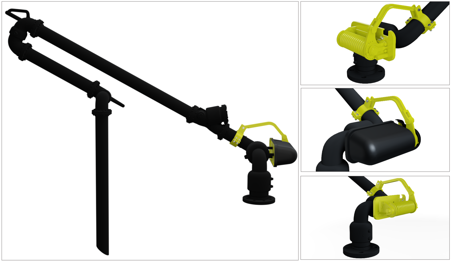
TORSION SPRING
REDLANDS loading arms can be equipped with torsion spring counterbalances which allow for adjustments to ensure a safe and perfectly balanced loading arm. The torsion spring sub assembly is a solid and compact system that is mounted directly on the base swivel joint. It is especially suitable where maximum free space is required.
We supply torsion spring assemblies for light duty as well as for heavier services. The torsion spring assembly moves a single spring that harnesses the energy as the arm is lowered, and when he arm is released the energy retained in the spring is released and the loading arm is raised.

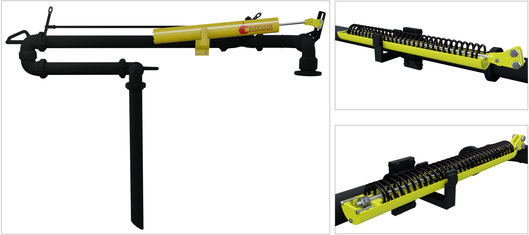
COMPRESSION SPRING
Loading arms equipped with compression spring counterbalance provide easy adjustment and gain significant space on platforms that need the whole area around the base swivel joint

NOMINAL DIAMETER SELECTION:
The flow of the product through the piping of the loading arm generates static energy and pressure drop.
The amount of energy generated is determined according to the composition of the fluid and the flow rate (flow). A simple empirical formula relating linear speed and arm diameter was developed to minimize the generation of load in the system:
vd <0.5 m² / sec.
Where
v = speed in meters per second.
d = internal diameter of the pipe in meters.
In addition, the linear flow velocity should never exceed 7 meters per second.
The 0.5 m² / sec limit. does not guarantee that static ignition will not occur, however, it significantly reduces this probability. This does not exempt from the obligation to use an effective grounding system in accordance with the current protection standards.
DIAMOND TABLE x FLOW (vd <0.5):
| NOMINAL PIPE DIAMETER | INTERNAL DIAMETER | FLUID SPEED | VD (CONSTANT <0.5) | MAX FLOW. | |
| (pol) | (mm) | (m/s) | (m²/s) | (LPM) | (m³/h) |
| 1.1/2″ | 40,9 | 7 | 0,286 | 553 | 33 |
| 2” | 52,5 | 7 | 0,368 | 908 | 54 |
| 3” | 77,9 | 6,41 | 0,5 | 1836 | 110 |
| 4” | 102,3 | 4,89 | 0,5 | 2411 | 144 |
| 5” | 128,2 | 3,9 | 0,5 | 3020 | 181 |
| 6” | 154,1 | 3,24 | 0,5 | 3630 | 217 |
| 8” | 202,7 | 2,47 | 0,5 | 4769 | 286 |
| 10” | 254,5 | 1,96 | 0,5 | 5980 | 358 |
| 12” |
303,2 | 1,65 | 0,5 | 7154 | 429 |
Redlands adopts as an internal procedure, dimensioning the arm considering the maximum flow allowed by the API standard 15% below its limit. In this way, we avoid hammer at the beginning of the operation, possible excess pressure in the line and ease the positioning of the arm in the compartment manhole of the truck.
In addition, to define the appropriate arm diameter, the pressure drop generated in the equipment must be analyzed (see table below), opting for a larger gauge if this pressure drop exceeds the limits established in the pumping system.
PRESSURE DROP TABLE:

